9 way clap switch circuit Clap activated switch circuit diagram Switch clap circuit diagram electronics gif fan transistor making projecct electrical engineering light
Make a Simple Electronic Clap Switch Circuit | Circuit Diagram Centre
Clap switch diagram block switching fig ijser paper
Clap based fan switching system
Clap switch circuitClap bc547 transistor circuits cd4017 Electrical & electronics engineering projecct: clap switch making diagramCircuit diagram of clap activated switch.
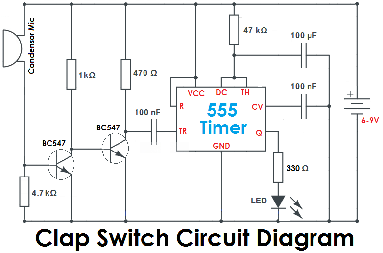
Clap switch circuit using 555Make a simple electronic clap switch circuit Clap switch off circuit diagram 555 using ic timer electronics circuitdigest projects automation sound electronic circuits mic condenser switching dcClap switch circuit with relay.

Clap switch circuit diagram using ic 555
Clap on-off switch with 4017 ic & bc547 transistorClap switch circuit simple make diagram components working electronicshub article diy Clap circuit switch diagram circuitdigest electronic arduino power sound sensor led project circuits block condenser 9v gif board amplifier batteryClap transistor.
Clap circuit fanSimple clap switch circuit using transistor Clap circuit 4017 cd4017 mic condenserClap block switching system fan diagram based.

Clap switch circuit using 555 ic and bc-547
Simple clap switch circuit using 555 timerClap activated light circuit diagram switch gadgetronicx using circuits simple sensor switching flip flop amp op projects schematic relay electronic Clap switch circuit 555 using timer ic electronic project electronics projects led mini bc diagram capacitors components resistors simple soundClap switch circuit diagram using ic 555.
Electronic schematic circuit diagramClap switch Circuit diagram of the clap activated switch (ojeleke & olawale, 2014Clap on clap off switch circuit diagram using 555 timer ic.
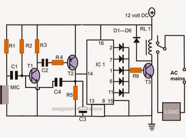
Clap switch circuit using ic 4017
Clap activated light circuitSwitch clap circuit electronic simple make diagram circuits two projects board sound description choose activated electronics homemade How to make simple clap switch automationSimple clap switch circuit using transistors (tested).
How to make simple clap switch: circuit, working?Activated clap olawale switch Clap switch : circuit diagram, working and its applicationsClap switching.

Clap operated switch circuit diagram
Circuit clap switch transistor simple usingCircuit switch clap diagram 555 using ne555 sound ic timer projects relay clock ic2 transistor electronics each output generated used Very simple clap switch circuit for on/off light and fan..simple clapClap circuit switch its diagram working.
Clap circuit transistors bulb tested makingcircuits transistor works multivibrator bistable timer artigoClap switch circuit using ic 555 Clap switch : circuit, working, advantages & its disadvantagesSwitch clap circuit schematic relay latching using coil single electroschematics triangle frame.

Clap switch electronic project
Clap circuit electronic relay schematic 220vClap switch circuit simple electronic using circuits cd4017 ic make relay readers provided keen above me Clap switch : circuit diagram, working and its applicationsBuilding a clap switch circuit: a step-by-step guide.
.